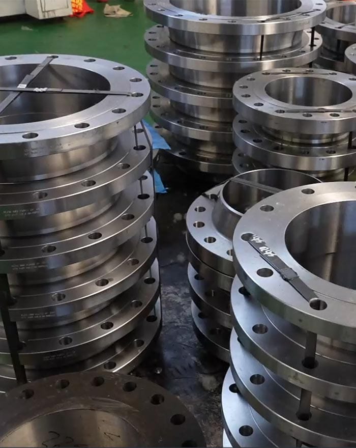
Choosing between two flanges with the same nominal size and pressure class may appear straightforward. However, the real difference between slip on vs weld neck flange designs becomes clear only after considering welding quality, pipe loading, temperature changes, vibration, maintenance access and the consequences of joint failure.
A flange that performs adequately in a low-risk water line may not be appropriate for a high-temperature process pipeline. At the same time, using the most robust flange design in every location can increase fabrication complexity without delivering a meaningful operational benefit.
This guide approaches slip on vs weld neck flange selection from a risk-based perspective. Instead of asking which flange is universally better, it explains how buyers, engineers and contractors can match the flange connection to actual project conditions.
Key Takeaways
- Slip on flanges are positioned over the pipe and normally require welds on both the inside and outside.
- Weld neck flanges use a tapered hub and a butt-welded connection to create a smoother load transition.
- Pressure class alone does not determine which flange should be used.
- Temperature cycles, vibration, external loads and failure consequences must also be evaluated.
- Flange material, facing, bore, pipe schedule and dimensional standard must be specified together.
- Inspection and documentation requirements should be included in the RFQ before production begins.
Table of Contents
Why Flange Selection Should Begin with Project Risk
The most useful way to evaluate slip on vs weld neck flange options is to begin with the operating risk of the pipeline.
A flange joint is not an isolated component. It is part of a system that includes the pipe, welds, gasket, bolting, supports and connected equipment. Even when the flange itself meets the required dimensional standard, poor selection or installation can reduce the reliability of the complete joint.
Before selecting a flange, consider four basic questions:
- What happens if the joint leaks?
- How frequently will the pipeline experience temperature or pressure changes?
- Will the connection be exposed to vibration or external bending?
- How easy will it be to inspect, repair or replace the joint?
A low-pressure utility water line in an accessible area presents a different risk profile from a process line carrying a hazardous or high-temperature fluid. This is why a slip on vs weld neck flange decision should not be based only on initial fabrication convenience.
Consequence of Failure
The greater the consequence of leakage, the more attention should be given to weld configuration, joint stiffness, fatigue resistance and inspection access.
Loading Conditions
Pipeline loads may come from internal pressure, thermal expansion, vibration, equipment nozzles, support settlement or misalignment. A connection that performs well under steady internal pressure may behave differently under repeated bending.
Maintenance Environment
A flange installed in an open utility area is easier to monitor than one located inside insulation, underground, at height or within a congested process unit.
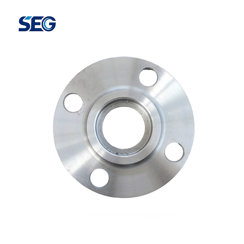
What Is a Slip On Flange?
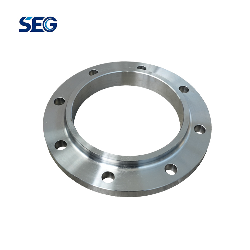
A slip on flange has a bore that allows the pipe to slide into the flange body. The flange is positioned on the pipe before welding, and the pipe end is normally set back from the flange face.
The connection generally uses:
- One fillet weld on the outside of the flange;
- One fillet weld inside the flange bore;
- A controlled gap between the pipe end and flange face.
You can review the available Slip On Flange configurations when preparing a project specification.
Why Buyers Choose Slip On Flanges
Slip on flanges can simplify alignment during workshop fabrication because the flange can be moved along the pipe before the welds are completed. They are frequently considered for moderate-duty piping where severe cyclic loading is not expected.
Their shorter hub also makes them useful where installation space is limited.
Important Limitations
The apparent simplicity of a slip on flange does not eliminate the need for accurate fabrication. The pipe insertion depth, internal weld, external weld and flange-face protection must all be controlled.
If the pipe is pushed too far toward the face, welding heat or weld metal may affect the gasket seating area. If the pipe is not inserted far enough, the internal geometry and weld arrangement may differ from the approved fabrication procedure.
What Is a Weld Neck Flange?
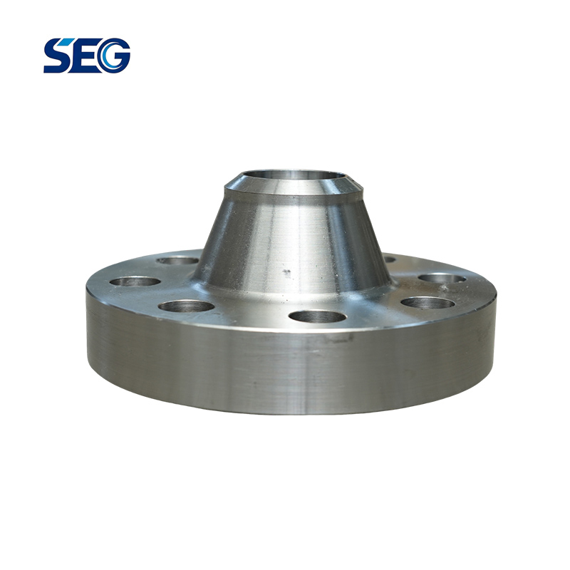
A weld neck flange has a long, tapered hub and is joined to the pipe with a full-penetration butt weld. The bore of the flange is selected to match the internal diameter associated with the pipe wall thickness.
The tapered hub helps transfer stress more gradually from the flange body into the pipe. This geometry is one reason weld neck flanges are frequently considered for demanding pressure, temperature and cyclic service.
The company’s Weld Neck Flange page provides an overview of available materials and applicable project standards.
The Role of the Tapered Hub
The hub is not merely a visual difference. It creates a transition between the thicker flange body and the connected pipe.
A smoother change in section can be important where a pipeline is exposed to:
- Repeated heating and cooling;
- Pressure fluctuations;
- Mechanical vibration;
- External bending loads;
- Equipment nozzle movement.
Butt-Welded Connection
Because the connection is butt welded, the flange bore and pipe bore can be aligned to create a relatively continuous internal flow path.
However, this benefit depends on correct bore matching, end preparation, fit-up and welding procedure control.
Slip On vs Weld Neck Flange at a Glance
The following table summarizes the main slip on vs weld neck flange differences.
| Evaluation Point | Slip On Flange | Weld Neck Flange |
|---|---|---|
| Connection method | Internal and external fillet welds | Full-penetration butt weld |
| Hub design | Short hub | Long tapered hub |
| Pipe insertion | Pipe enters flange bore | Pipe end aligns with flange neck |
| Bore matching | More insertion tolerance | Should match pipe wall and bore |
| Fabrication alignment | Relatively easy before welding | Requires accurate end alignment |
| Cyclic loading | Better suited to less demanding cycles | Commonly selected for demanding cyclic service |
| High-temperature use | Requires careful engineering review | Often preferred for severe temperature service |
| Vibration | May be acceptable for moderate conditions | Often selected where vibration is significant |
| Internal flow transition | Internal weld and pipe end remain in flow path | Smoother transition when correctly matched |
| Weld inspection | Fillet weld inspection | Butt weld can support volumetric examination |
| Space requirement | Shorter overall connection | Longer hub requires more space |
| Typical selection basis | Fabrication simplicity and moderate service | Reliability under demanding operating conditions |
The table is a screening tool, not a replacement for the piping design code or project specification. The final slip on vs weld neck flange choice must be reviewed against the actual service conditions.
How Pressure and Temperature Affect the Decision
One of the most common mistakes is assuming that pressure class alone determines whether a flange is suitable.
A Class 150, Class 300 or higher class designation does not act independently. Allowable service conditions depend on material group, temperature, applicable code and the selected standard.
The current ASME B16.5 standard addresses pressure-temperature ratings, dimensions, materials, tolerances, marking and testing for covered flanges and flanged fittings.
Steady Pressure Service
For a stable, moderate-pressure pipeline with limited temperature change and low external loading, either flange type may be technically possible when permitted by the project code.
The decision may then depend on fabrication methods, inspection requirements, installation space and maintenance strategy.
High-Temperature Service
As temperature rises, thermal expansion becomes more important. Pipe movement can introduce bending and rotation at flange connections, especially when supports and expansion flexibility are not properly coordinated.
In a slip on vs weld neck flange comparison for high-temperature service, the gradual hub transition and butt-welded connection of the weld neck design are often important advantages.
Cyclic Pressure and Temperature
Repeated startup, shutdown, heating, cooling or pressure variation can produce fatigue loading. A pipeline may remain below its maximum design pressure while still experiencing damaging stress cycles.
For cyclic service, buyers should ask for engineering confirmation rather than selecting a flange only from a general pressure-class table.
Welding and Installation Differences
Welding is one of the most important distinctions in the slip on vs weld neck flange decision.
Slip On Flange Welding
A slip on connection normally requires two fillet welds. Although each weld may be simpler than a butt weld, the total process still requires:
- Correct pipe insertion;
- Controlled flange-face setback;
- Internal bore access;
- External weld access;
- Distortion control;
- Cleaning of both weld areas.
Internal Weld Access
The internal fillet weld can be difficult to complete or inspect on small sizes, restricted assemblies or prefabricated spools.
Buyers should confirm that the fabricator can access the internal weld without damaging the flange face.
Flange-Face Distortion
Excessive or poorly sequenced heat input can distort the flange. Distortion may affect alignment, gasket compression and final leak tightness.
Weld Neck Flange Welding
A weld neck flange requires pipe-end preparation and accurate butt-weld fit-up. Depending on the project, the weld may be examined using radiographic or ultrasonic methods.
Important controls include:
- Correct bevel geometry;
- Root opening;
- Internal alignment;
- Approved welding procedure;
- Qualified welder;
- Preheat or post-weld heat treatment where required;
- Nondestructive examination.
A weld neck flange may demand more preparation, but the finished joint offers a continuous welded transition between the pipe and flange neck.
Which One Is Easier to Install?
There is no single answer.
A slip on flange can be easier to position before welding, particularly in a fabrication shop. A weld neck flange can be more straightforward to inspect as a butt-welded joint when the project already has established pipe welding and NDT procedures.
Therefore, slip on vs weld neck flange installation difficulty depends on fabrication capability, pipe size, access, inspection level and workforce experience.
Bore Alignment, Flow and Corrosion Considerations
Flange selection can influence the internal condition of the pipeline, not only its external strength.
Bore Continuity
A weld neck flange should be ordered with a bore that corresponds to the connected pipe wall thickness. When the bore and pipe are correctly matched, the transition can remain smooth.
A mismatch may create an internal step, increase turbulence or complicate welding.
Internal Geometry of Slip On Flanges
A slip on flange contains the pipe end and internal fillet weld within the flange bore. In many services, this does not create a major operational problem.
However, it deserves closer attention when the fluid contains:
- Solids;
- Abrasive particles;
- Corrosive deposits;
- Product that can accumulate in crevices;
- Material that requires frequent internal cleaning.
Crevice and Deposit Risk
The internal geometry of a connection may create local areas where deposits collect. The importance of this risk depends on the fluid, velocity, temperature, cleaning process and corrosion allowance.
The slip on vs weld neck flange comparison should therefore include process cleanliness and corrosion behavior, especially in chemical, wastewater and slurry systems.
Material, Facing and Standard Compatibility
Selecting the flange type is only one part of the specification. A technically correct RFQ must also define material, standard, pressure class, facing, bore and pipe compatibility.
Material Selection
Common flange materials include:
- Forged carbon steel;
- Stainless steel;
- Alloy steel;
- Duplex stainless steel;
- Low-temperature steel.
For carbon steel forged piping components, ASTM A105/A105M covers flanges, fittings, valves and similar forged components intended for pressure systems at ambient and higher-temperature conditions.
Material selection should account for:
- Design temperature;
- Fluid corrosiveness;
- Required mechanical properties;
- Low-temperature toughness;
- Welding compatibility;
- Project material specification;
- Regulatory requirements.
Dimensional Standards
The quotation must state the exact dimensional system. Do not submit an RFQ that says only “standard flange.”
For many industrial projects, buyers may specify an ASME class-based system. Other projects may use a PN-based flange system.
ISO 7005-1 establishes a base specification for steel pipe flanges used in general and industrial piping systems and places responsibility for selecting the appropriate flange series with the purchaser.
Components from different dimensional systems should not be assumed to be interchangeable.
Flange Facing
Common facing requirements include:
- Raised face;
- Flat face;
- Ring-type joint;
- Other project-specific facing details.
The flange facing must be compatible with the mating flange and gasket design. A mismatch can prevent proper assembly even when nominal size and pressure designation appear similar.
Pipe Wall and Bore
For weld neck flanges, include the pipe schedule, wall thickness or required bore.
For slip on flanges, confirm that the flange bore suits the pipe outside diameter and that the required insertion and welding arrangement can be achieved.
Inspection and Quality Documentation
The quality plan should reflect the risk of the service.
A utility pipeline and a critical process pipeline may use similar-looking flanges but require very different levels of documentation and inspection.
Dimensional Inspection
Typical checks include:
- Outside diameter;
- Flange thickness;
- Hub dimensions;
- Bore diameter;
- Bolt-hole quantity and diameter;
- Bolt-circle diameter;
- Facing dimensions;
- Overall height;
- Flatness and alignment.
Material Verification
Depending on the project, buyers may request:
- Material test certificates;
- Heat-number traceability;
- Chemical composition results;
- Mechanical property results;
- Positive material identification;
- Hardness testing;
- Impact testing where applicable.
Weld Examination
In a slip on vs weld neck flange quality plan, the weld type affects the available inspection method.
Fillet welds are commonly evaluated using visual and surface examination methods. Butt welds may also permit volumetric examination where specified and technically practical.
The required NDT method, examination percentage and acceptance criteria must be stated in the purchase specification.
Joint Assembly
Flange quality does not guarantee a leak-tight joint if assembly is poorly controlled.
ASME PCC-1 provides guidance for pressure-boundary bolted flange joint assembly, including procedures that can support cleaning, inspection, gasket installation, alignment and tightening practices.
Application-Based Decision Matrix
The following matrix provides a practical starting point for slip on vs weld neck flange selection.
| Project Condition | Initial Direction | Reason for Review |
| Moderate-pressure utility water | Slip on may be considered | Stable service and accessible maintenance |
| General low-risk plant piping | Evaluate both | Final choice depends on code and fabrication plan |
| High-temperature process line | Weld neck commonly preferred | Thermal expansion and connection loading |
| Frequent startup and shutdown | Weld neck commonly preferred | Cyclic stress and fatigue considerations |
| Significant vibration | Weld neck commonly preferred | Smoother load transfer through the hub |
| Hazardous or highly consequential fluid | Weld neck often receives priority | Leakage consequence and inspection requirements |
| Restricted axial installation space | Slip on may offer an advantage | Shorter hub geometry |
| Heavy external nozzle load | Engineering analysis required | Flange type alone does not resolve system loading |
| Abrasive or deposit-forming fluid | Weld neck may offer a cleaner bore | Internal geometry should be reviewed |
| Workshop spool fabrication | Evaluate both | Capability, fit-up and inspection determine efficiency |
| Field modification with limited access | Project-specific review | Internal weld access may restrict slip on use |
| Severe corrosion service | Material and geometry review | Alloy selection and crevice conditions matter |
This table does not authorize a final design. It helps identify which questions must be resolved before ordering.
A Practical Slip On vs Weld Neck Flange Selection Process
A repeatable decision process reduces the risk of choosing a flange from habit.
Step 1: Confirm the Governing Code
Identify the piping code, client specification and dimensional standard before comparing flange designs.
Step 2: Define the Operating Envelope
Record:
- Design pressure;
- Design temperature;
- Minimum operating temperature;
- Normal operating conditions;
- Pressure cycles;
- Temperature cycles;
- Fluid properties.
Step 3: Evaluate Mechanical Loading
Review vibration, thermal expansion, pipe support arrangement, connected equipment and external moments.
Step 4: Review Failure Consequences
Consider personnel exposure, environmental impact, shutdown consequences and maintenance difficulty.
Step 5: Confirm Fabrication Capability
Determine whether the fabricator has the welding procedures, qualified personnel and inspection capability required for the proposed connection.
Step 6: Compare Lifecycle Risk
The slip on vs weld neck flange decision should consider inspection, maintenance, potential leakage and replacement difficulty, not only the amount of fabrication work.
Step 7: Freeze the Technical Specification
Do not request production until the size, class, material, facing, standard, bore, pipe schedule, inspection and documentation requirements are confirmed.
Information to Include in a Flange RFQ
An incomplete RFQ often produces quotations that cannot be compared accurately.
For either slip on vs weld neck flange option, include the following information.
Essential Technical Data
- Flange type;
- Nominal pipe size or DN;
- Dimensional standard;
- Pressure class or PN rating;
- Material grade;
- Flange facing;
- Pipe outside diameter;
- Pipe wall thickness or schedule;
- Required bore;
- Quantity.
Service Information
- Design pressure;
- Design temperature;
- Operating fluid;
- Corrosion requirements;
- Cyclic service conditions;
- Sour, low-temperature or special service where applicable.
Inspection Requirements
- Material certificate type;
- Heat-number traceability;
- Dimensional report;
- PMI requirement;
- NDT method and percentage;
- Hardness or impact testing;
- Third-party inspection;
- Final marking requirements.
Commercial and Delivery Details
- Required delivery schedule;
- Packaging method;
- Shipping marks;
- Documentation language;
- Drawing approval requirements;
- Destination;
- Any OEM marking or packaging instructions.
For assistance reviewing a flange specification or preparing a project quotation, buyers can contact the pipeline product team.
Common Slip On vs Weld Neck Flange Buying Mistakes
Choosing Only by Pressure Class
Two flanges may share the same class designation while behaving differently under external loads, vibration and thermal cycles.
Ignoring Pipe Schedule
A weld neck flange bore should correspond to the connected pipe wall. Omitting Schedule or wall thickness can result in an internal mismatch.
Mixing Dimensional Systems
An ASME class flange and a PN flange should not be treated as interchangeable merely because the nominal sizes appear similar.
Forgetting the Facing
A quotation that omits raised face, flat face or ring-type joint requirements may result in a flange that cannot mate with the existing system.
Assuming a Slip On Flange Needs Only One Weld
The approved fabrication detail must be followed. Buyers should not assume that an external fillet weld alone satisfies the project requirements.
Comparing Flanges Without Comparing Inspection
A lower-risk inspection plan and a higher-level inspection plan do not represent equivalent supply scopes.
Treating Every Pipeline the Same
The correct slip on vs weld neck flange selection for a water utility line may not be appropriate for steam, gas, chemical or cyclic process service.
FAQ
Is a weld neck flange always better than a slip on flange?
No. A weld neck flange offers advantages for many demanding services, but it is not automatically required in every pipeline. Moderate, stable and low-risk applications may permit a slip on flange when supported by the governing code and project specification.
Which flange is more suitable for high-pressure piping?
In a slip on vs weld neck flange comparison for high-pressure or high-consequence service, weld neck flanges are commonly selected because of their tapered hub and butt-welded connection. The final decision must still account for material, class, temperature and piping-code requirements.
Can slip on flanges be used at high temperatures?
Their use depends on the applicable code, material, design conditions, cyclic loading and client specification. High temperature alone should not be evaluated without considering thermal expansion and external connection loads.
Why does a slip on flange normally require two welds?
The internal and external fillet welds connect the pipe to both sides of the flange hub area. The exact weld detail must follow the approved design and fabrication procedure.
Why must a weld neck flange bore match the pipe schedule?
The flange neck and pipe should form a suitable internal transition. A significant mismatch can affect fit-up, welding and internal flow geometry.
Which flange is easier to align?
A slip on flange can be moved along the pipe before final welding, which can assist workshop positioning. A weld neck flange requires more accurate butt-weld alignment.
Which flange is better for vibration?
Weld neck flanges are often considered for vibration and cyclic loading because the tapered hub provides a gradual transition into the pipe. However, supports, equipment loads and system flexibility must also be reviewed.
Can slip on and weld neck flanges have the same pressure class?
Yes. Both may be produced in the same nominal class, but equal class designation does not mean equal connection geometry or equal suitability for every service.
What documents should be requested with industrial flanges?
Common documents include material certificates, heat-number records, dimensional reports, test results, NDT reports and inspection certificates. The required documents should be listed in the RFQ.
How should buyers make the final slip on vs weld neck flange decision?
Start with the governing code, operating conditions, cyclic loading, failure consequences, fabrication capability and inspection plan. Then compare the two designs using the complete project requirements rather than a single feature.
Conclusion
The slip on vs weld neck flange decision is not simply a comparison between an economical flange and a stronger flange. It is a system-level decision involving pressure, temperature, fatigue, vibration, welding, inspection, corrosion and maintenance.
Slip on flanges can be effective in appropriate moderate-duty services where fabrication flexibility and compact geometry are useful. Weld neck flanges are commonly selected when a project requires a smoother stress transition, butt-welded construction, improved bore continuity or a higher level of connection reliability.
The most reliable purchasing approach is to define the service conditions first and the flange type second. A complete RFQ should identify the standard, class, material, facing, bore, pipe schedule, testing and documentation requirements.
Cangzhou Sirgou supplies industrial pipe fittings and pipeline products for different project specifications. Buyers can compare the available Slip On Flange and Weld Neck Flange options or submit project requirements for technical review and quotation support.